Introduction
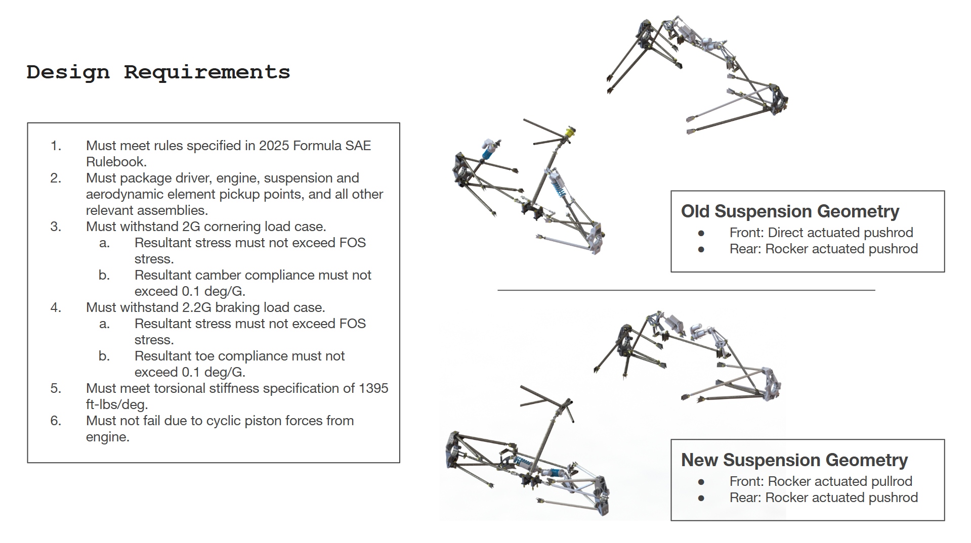
As the chassis subteam lead on Berkeley Formula Racing, I was in charge of project management throughout the chassis subteam as well as design, manufacturing, and validation of our steel space frame chassis. For our B25 racecar, our front suspension setup changed from direct actuated to rocker actuated pull rod, which meant that the structural load paths and stiffness behavior of the chassis changed considerable, and an overhaul of chassis geometry was necessary.
Design Specifications
Before solid part optimization began, I established design specifications for the chassis.
CAD
The chassis was CADed in Solidworks. I used the Skeleton Sketch Part technique to define the chassis master sketch, which allowed for rapid geometry iteration during the part design process.
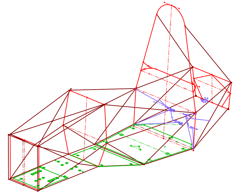
Chassis Skeleton part
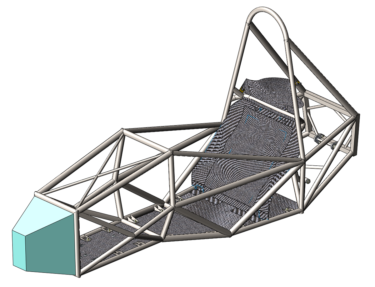
Full chassis assembly
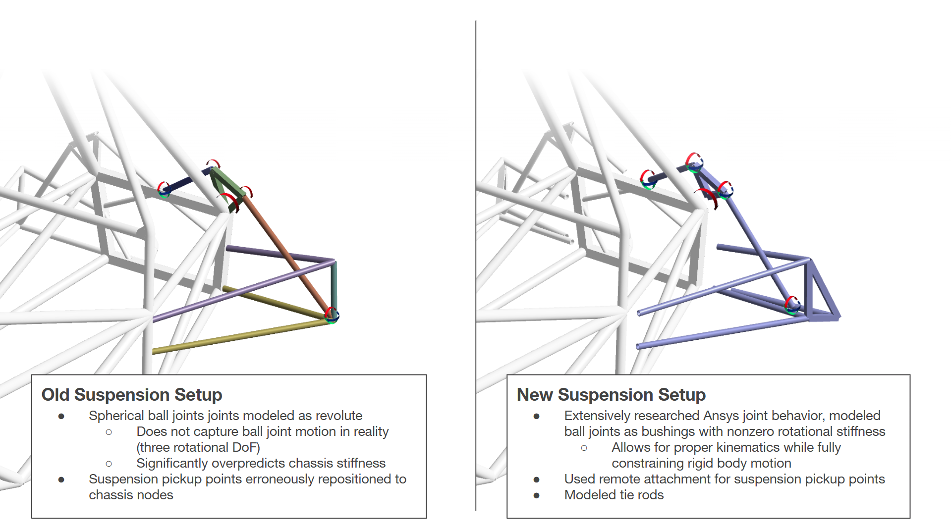
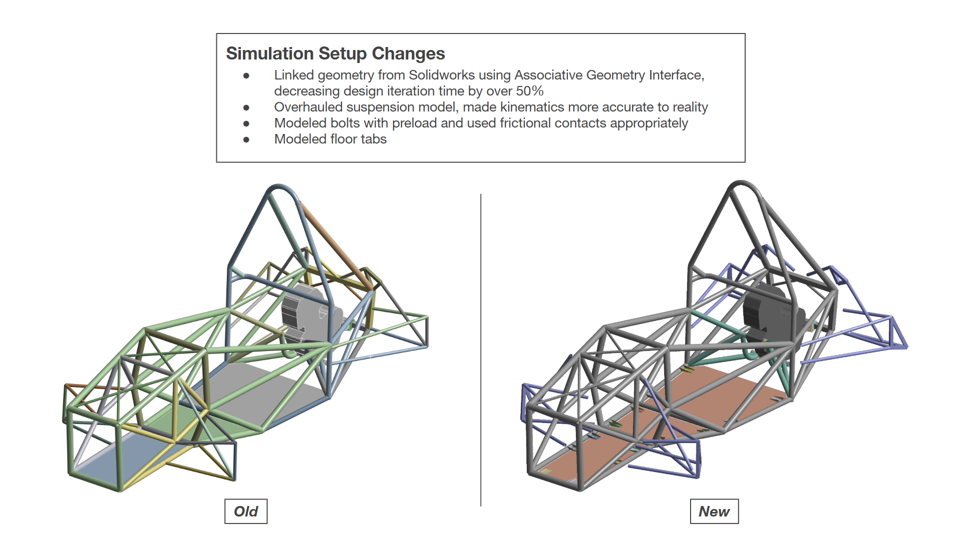
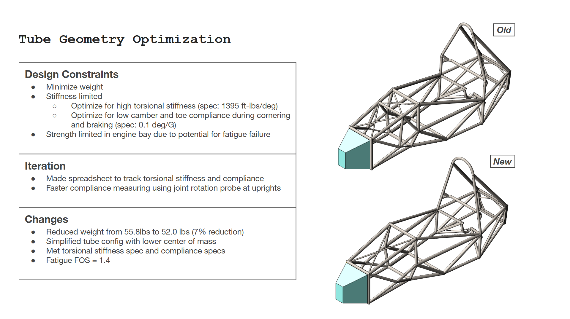
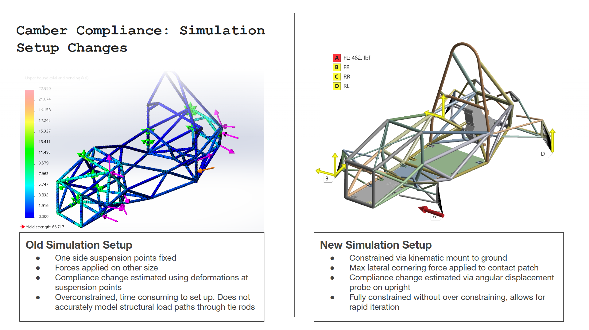
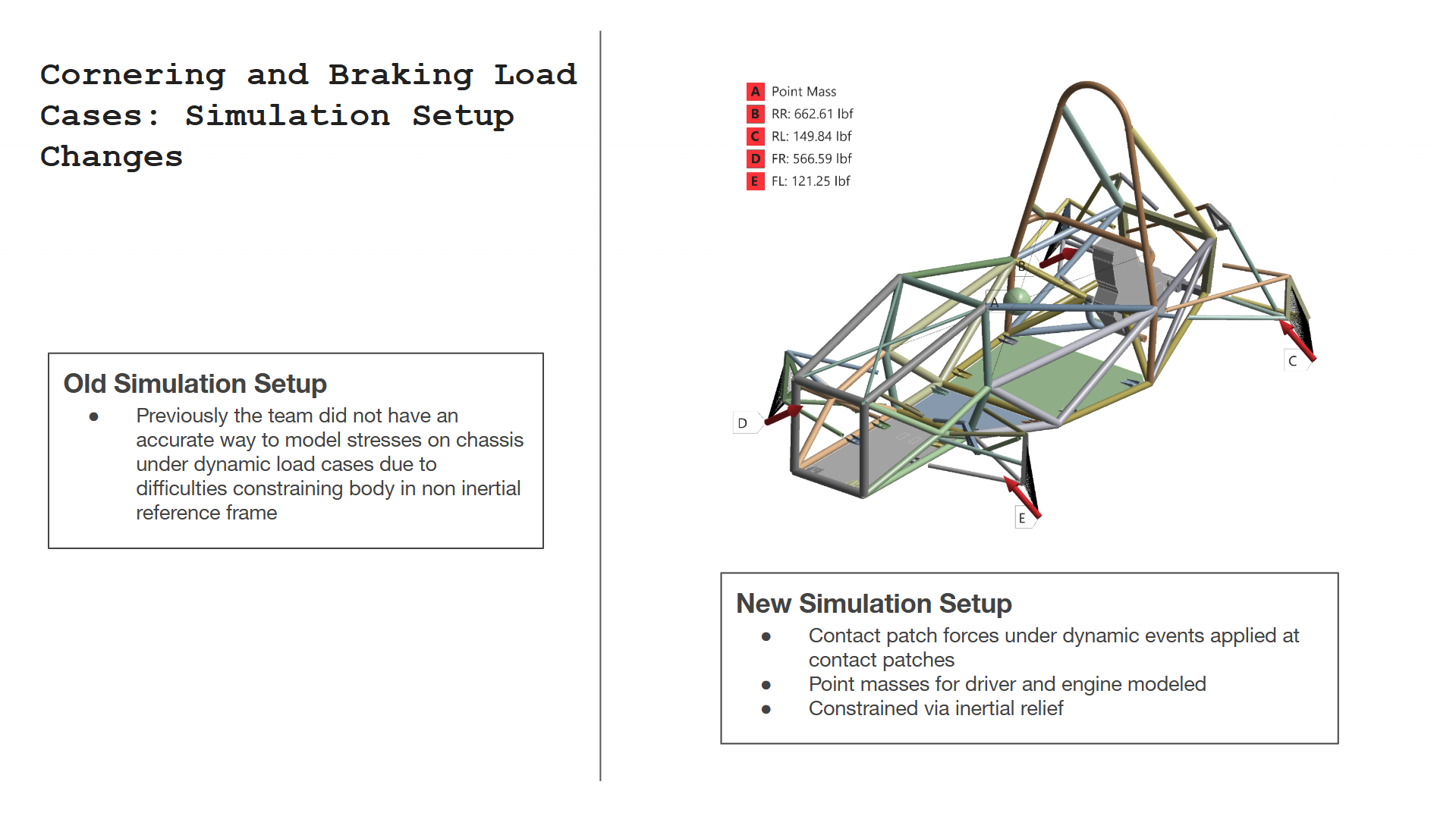
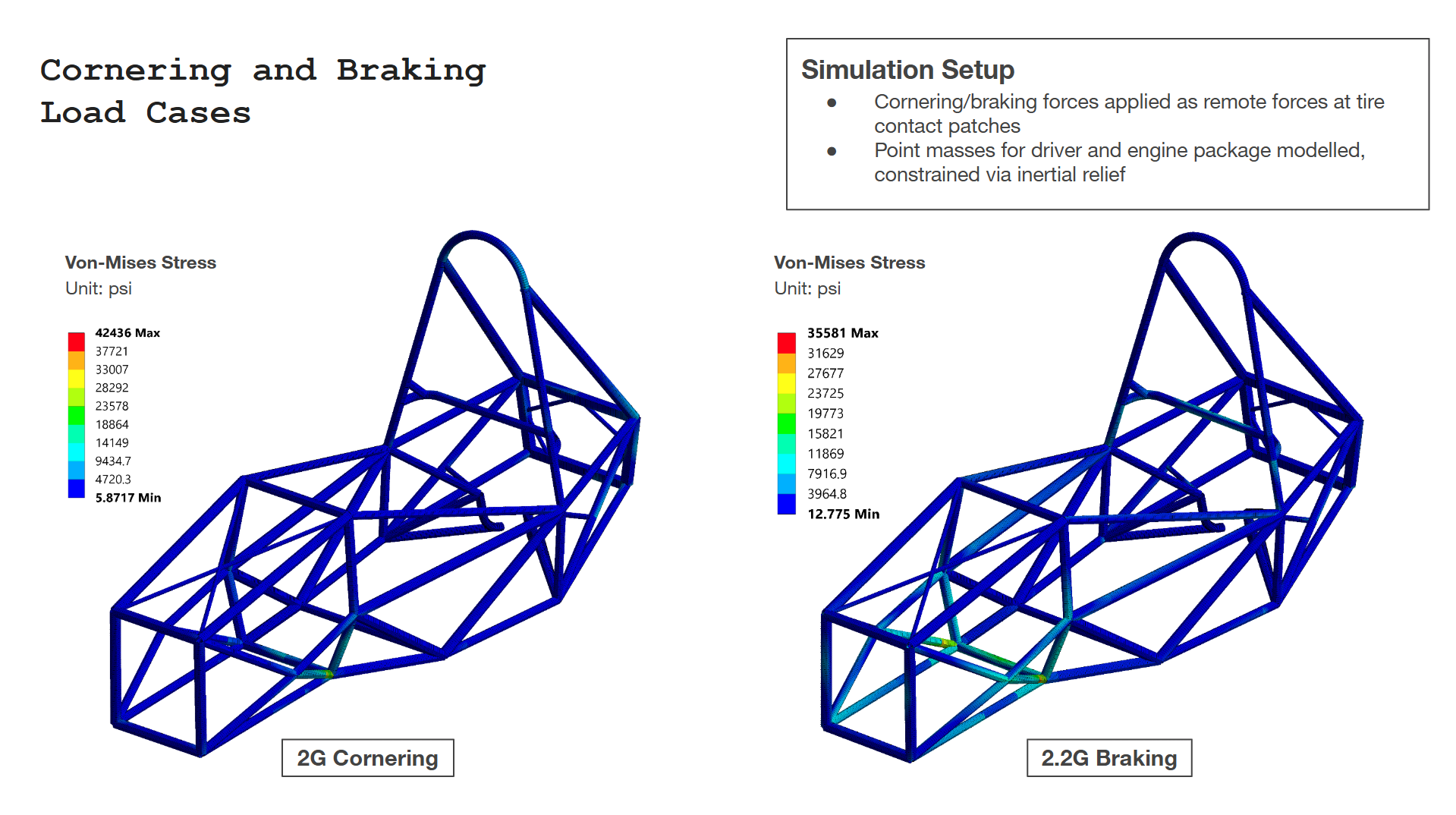
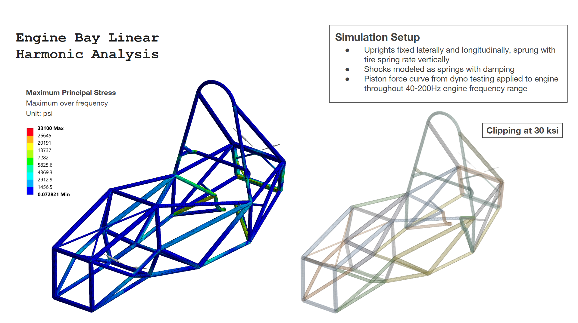
Optimization
As I began optimization of the chassis, a number of errors with our previous simulation setup became apparent.
Manufacturing
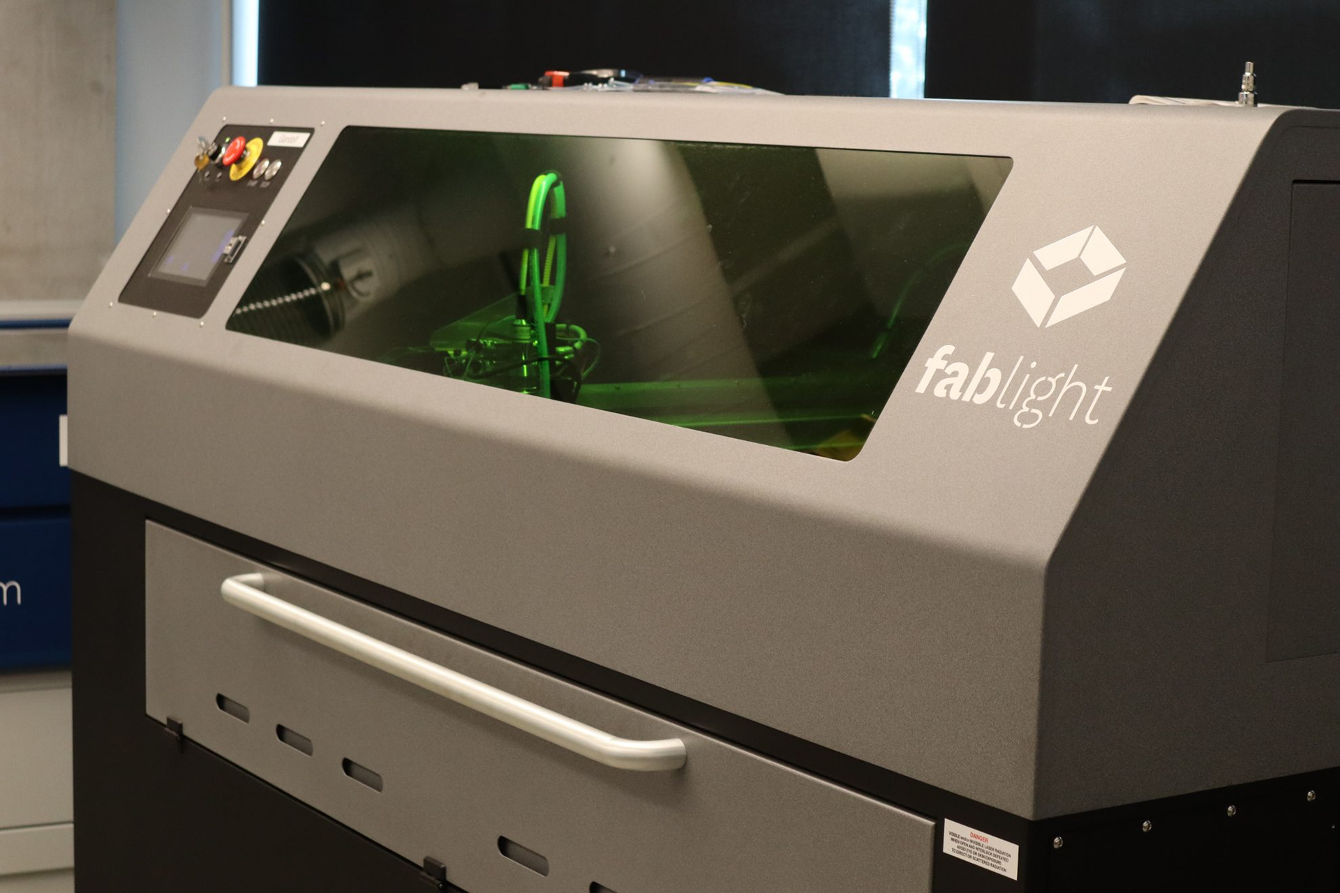
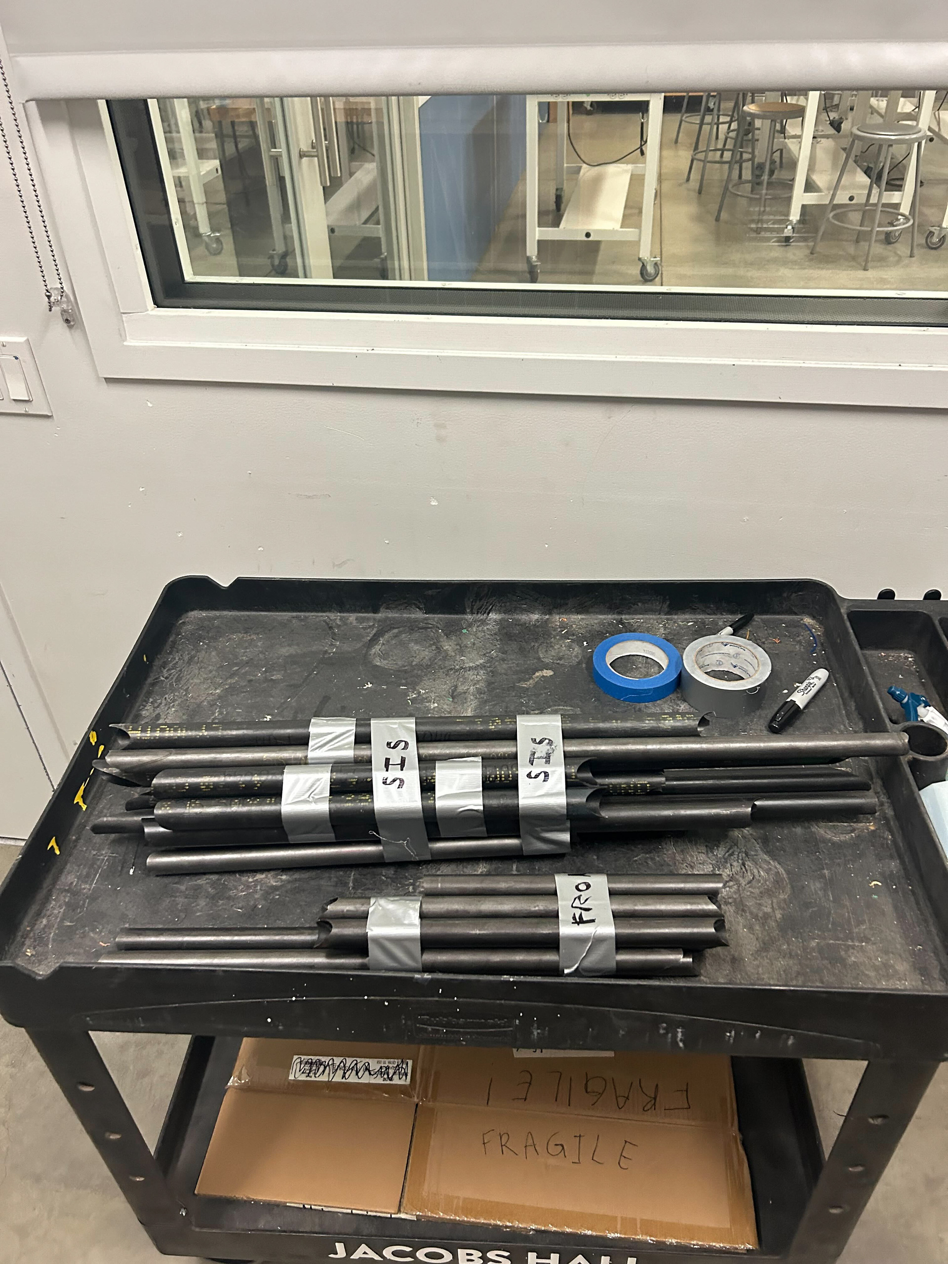
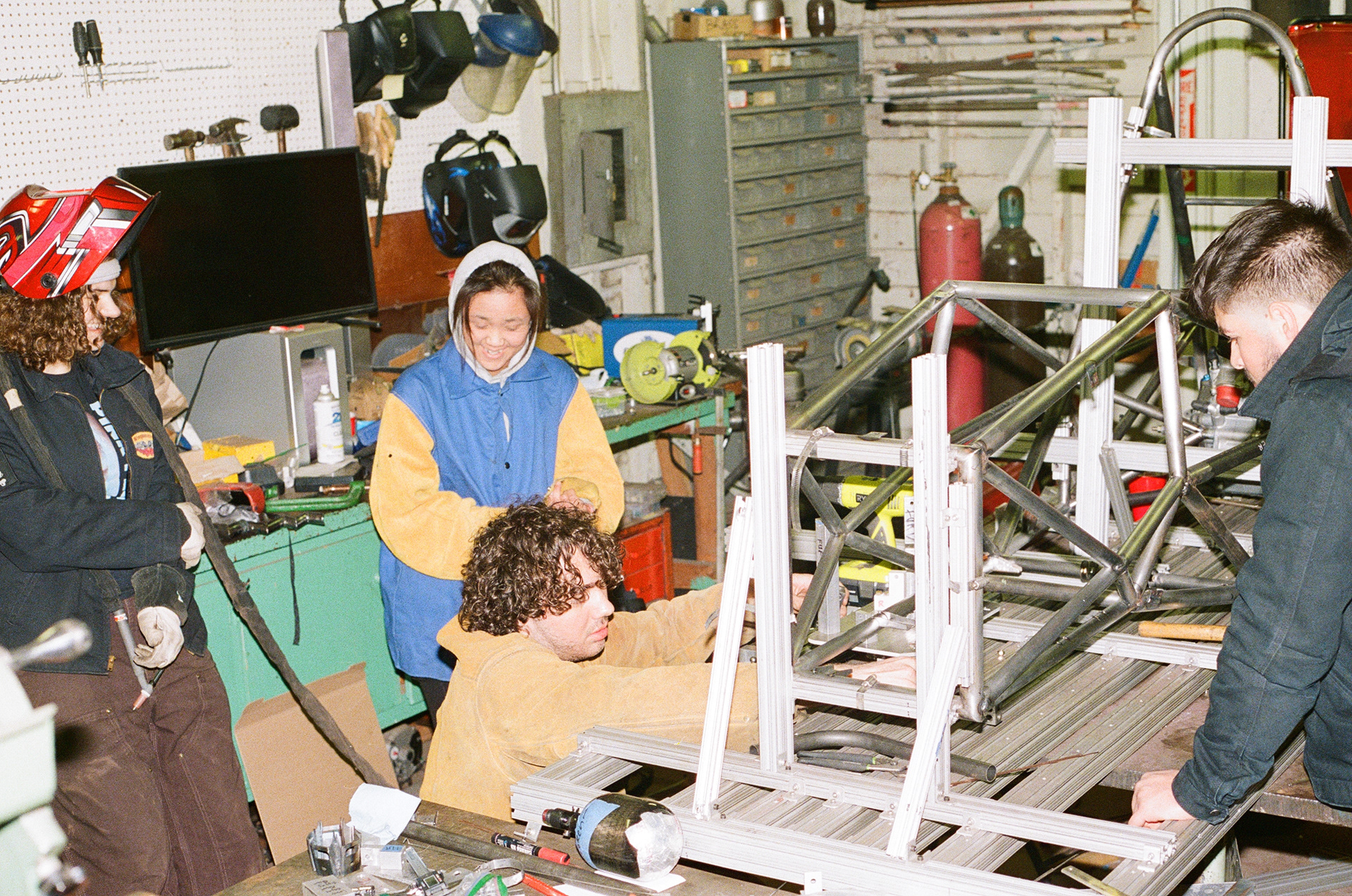
The chassis was TIG welded from 4130 Chromoly Steel. Over the prior summer, I learned to TIG weld and practiced welding various nodes while minimizing heat distortion. Previously, we had always outsourced our laser tube cutting to a vendor that charged us over $1000 and took around 3 weeks to cut tubes. I developed and organized a process for laser cutting tubes in-house which saved 2 weeks of time and was free, using our fablight laser cutter.
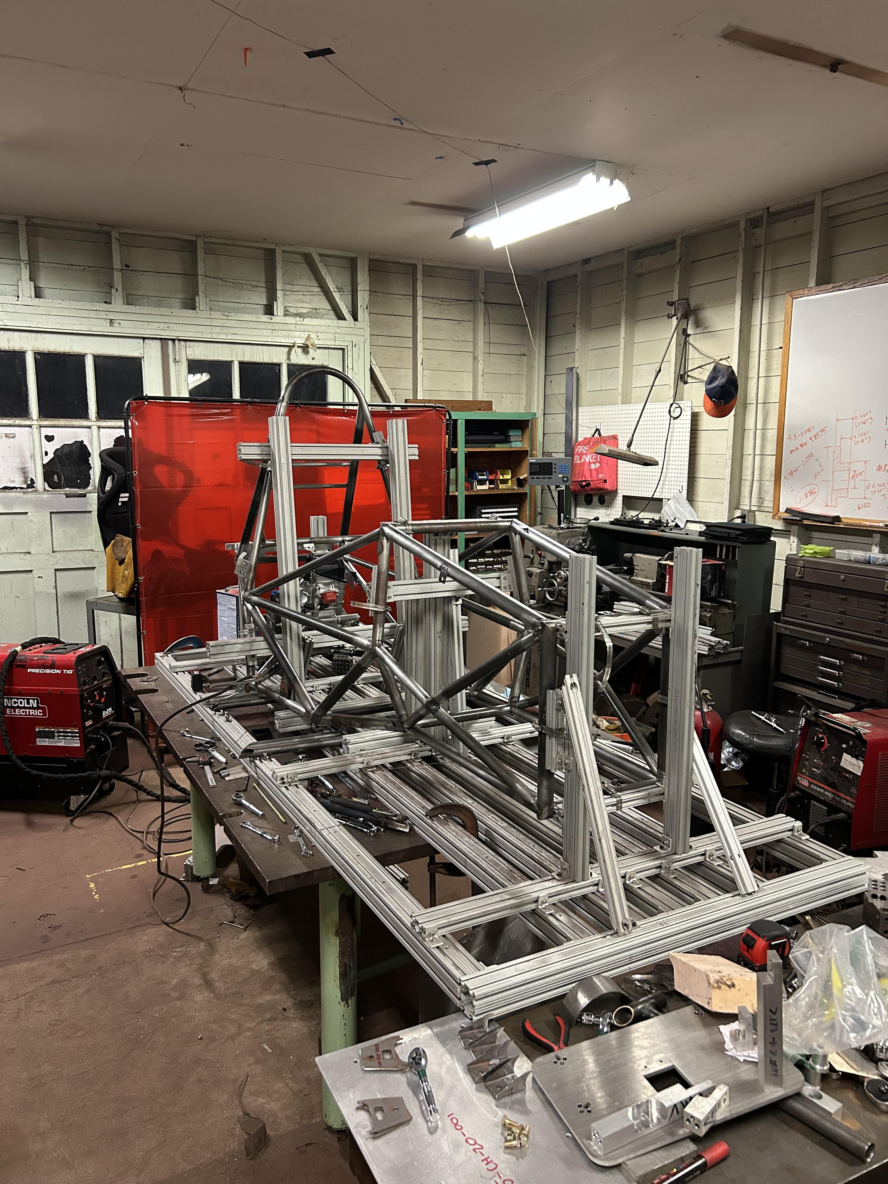
During the welding season, I led efforts in both overseeing the welding of all tubes, as well as manufacturing (waterjetting and milling) and constructing all fixtures to position tubes in place. Later on, I also collaborated with our Technical Director to coordinate all subsystem tab manufacturing and welding.
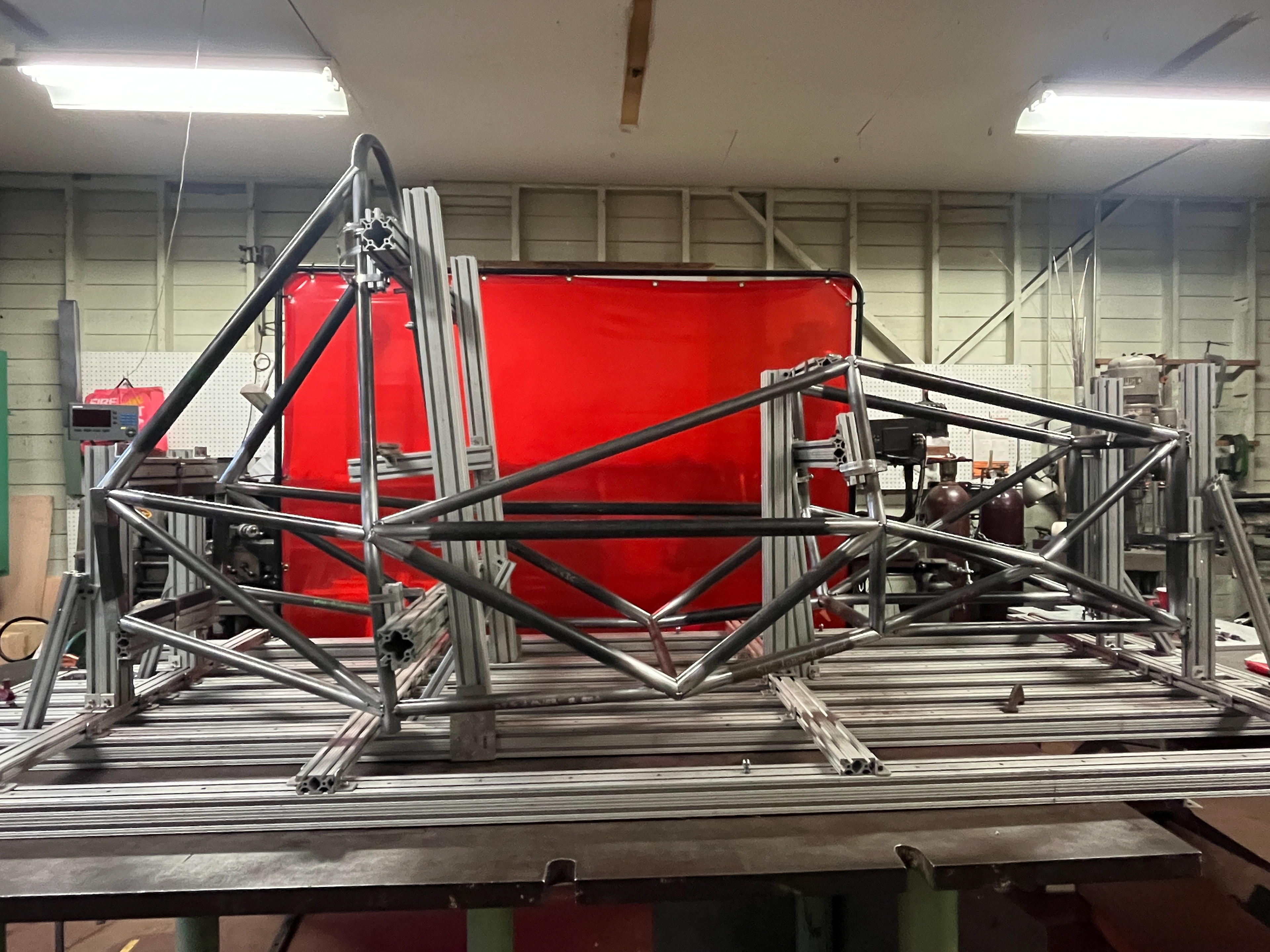
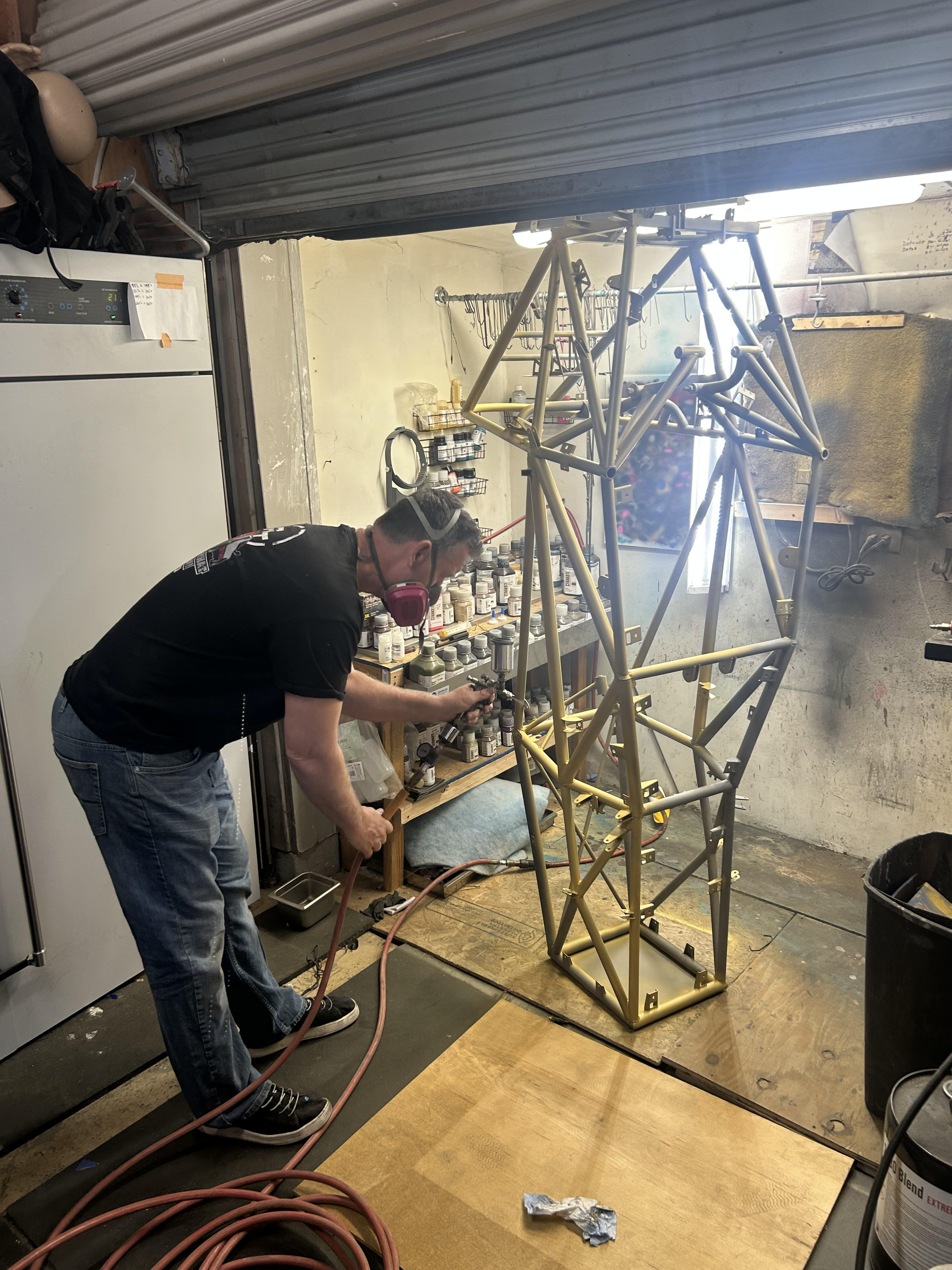
Once welding was finalized, we took the chassis to get coated. I chose a Cerakote ceramic coating as it was much lighter than traditional powder coating or painting.
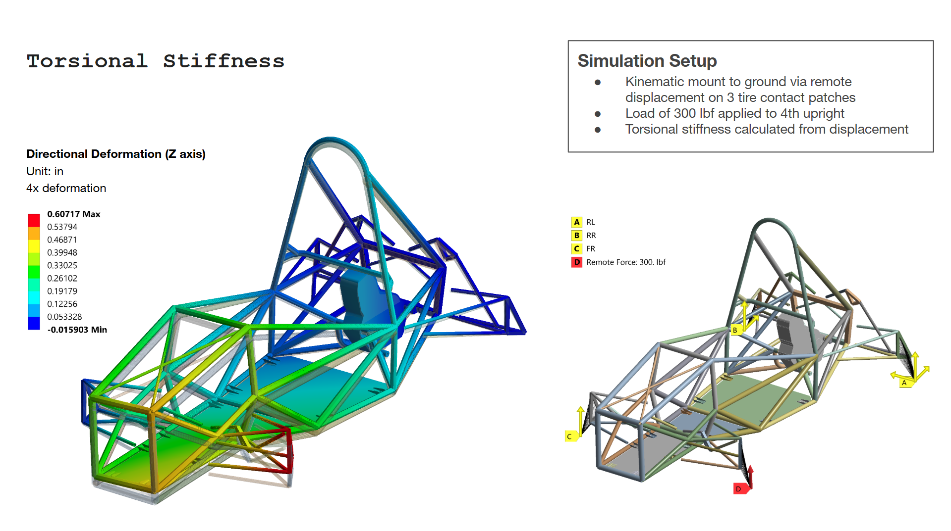
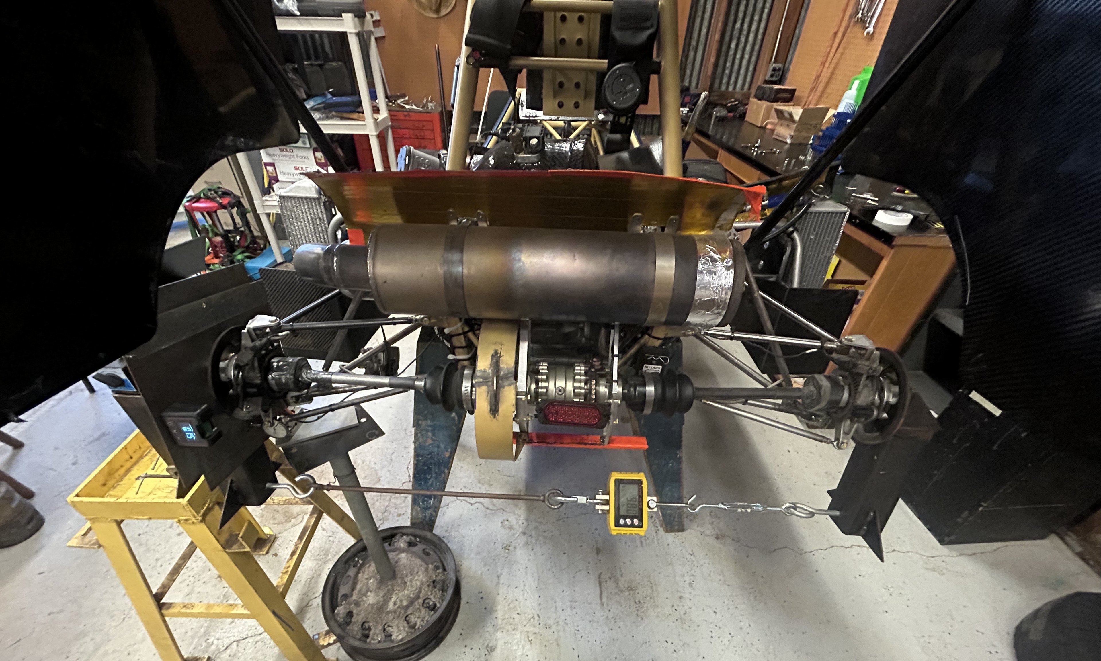
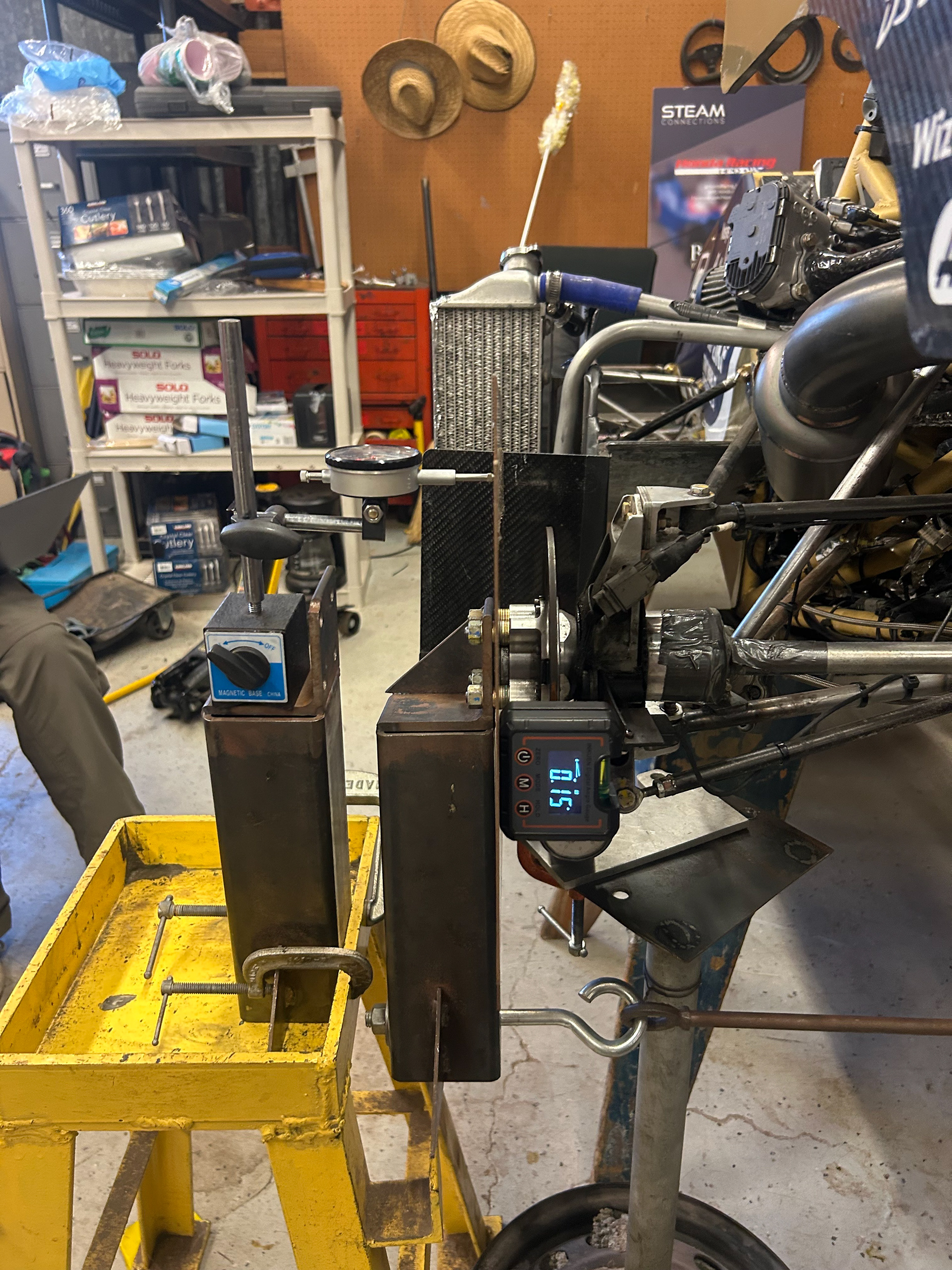
Validation
We validated both our Torsional Stiffness and camber compliance with rear life testing.
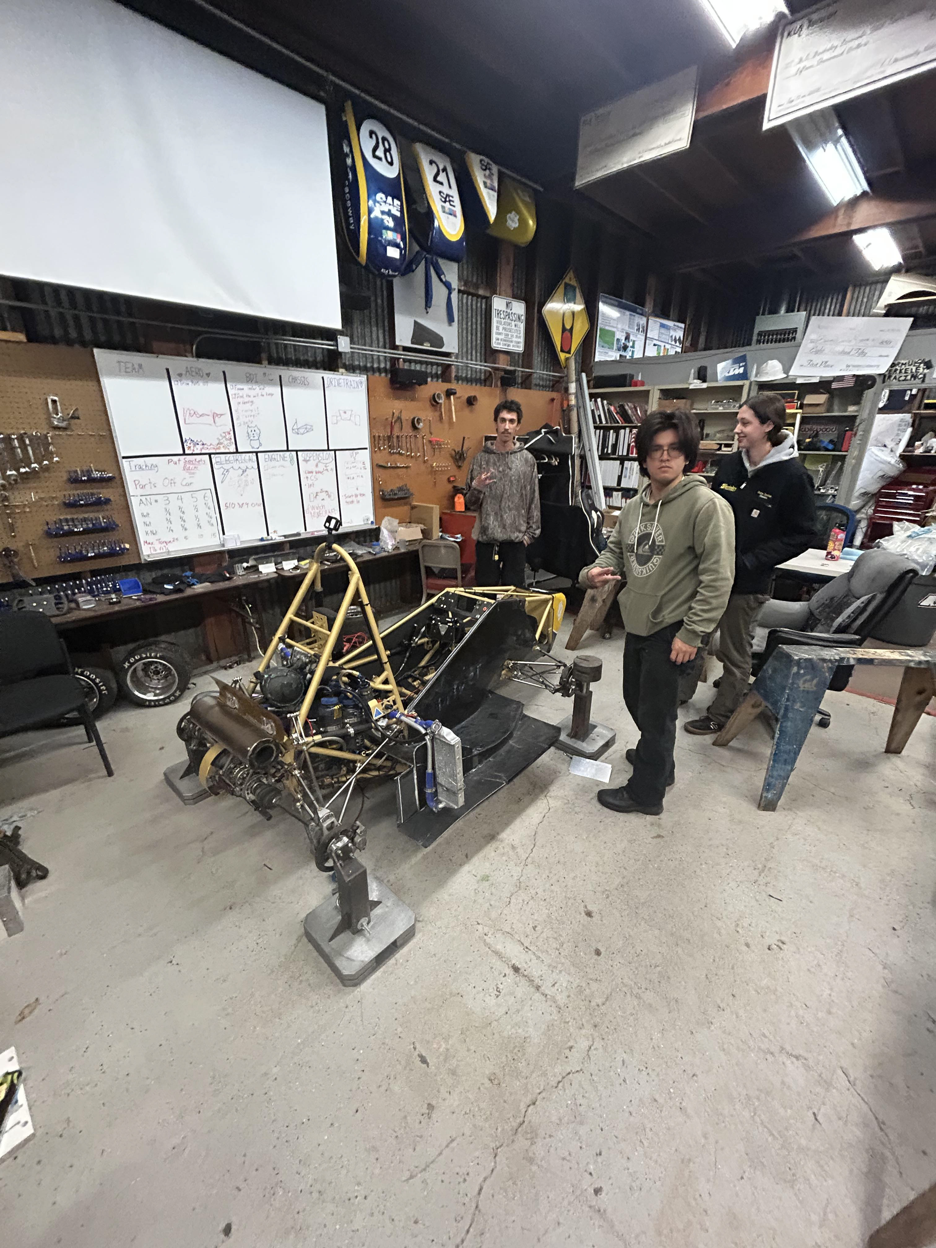
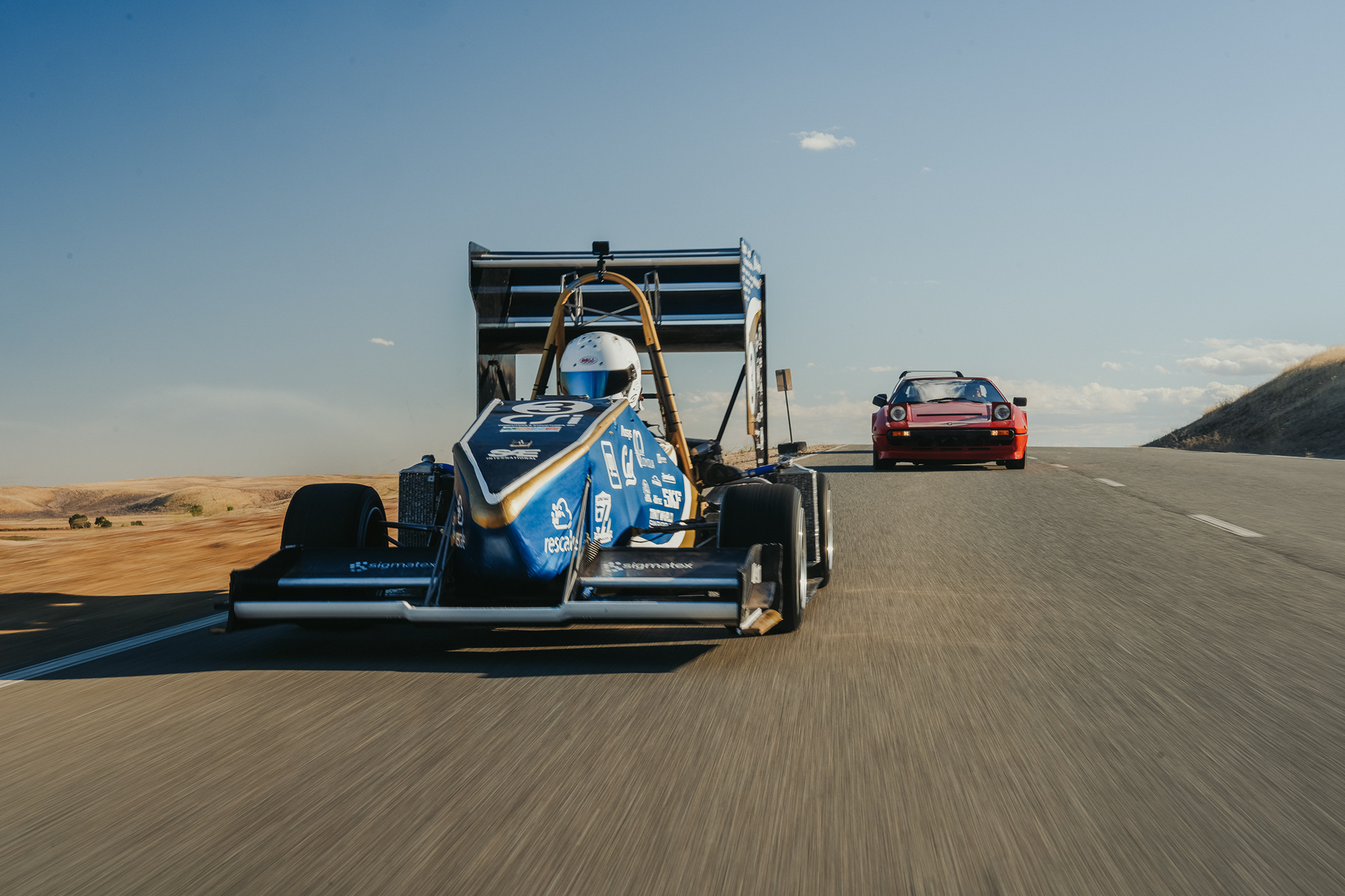
Our B25 car in action!